| Issue: |
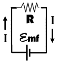
To the right is an example of a simple single loop circuit. In this exploration, we will learn how to solve this type of circuit and how to simplify more complicated circuits so that we can solve them, too.
|
|
 |
Discussion:
In this diagram, I is the current traveling in the direction of the arrows. R represents the resistor in the circuit. The emf is the source of electric potential (voltage) in the circuit that causes the current to flow. The first tool that we will use to investigate circuits is Ohm's Law:
 |
Here I is the current traveling through the resistor. V is the voltage drop across a resistor and R is the resistance of the resistor.
|
Now we are ready to solve the simple circuit.
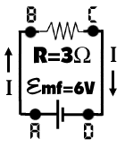
 In the diagram, we are given the resistance and the emf, so it seems that we are left to solve for the current in the wire. The first thing we need to do, though, is investigate how the potential (voltage) changes around the circuit. We can assume that at point a the voltage is 6 volts and then will break circuit into four regions to investigate following the current around the loop:
1. From A to B: There is no change in the potential, so between A and B potential remains 6 Volts.
2. From B to C: The potential must drop as the current crosses the resistor. Since this is the only resistor in the loop, the current must drop the full amount (6 Volts down to 0 Volts).
3. From C to D: Again no change in the potential, so it remains at 0 Volts.
4. From d to a: Now we cross the source of potential (emf), so the potential will increase by 6 Volts back up to six.
The loop rule does indeed hold true since in a complete loop we started at 6 Volts at point a and when we returned to point A we again had 6 Volts (you can see this rule will hold true for a complete loop started at any other point).
We know that the voltage drop across the resistor is 6 Volts and can now solve for the current.
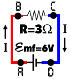
 Before we solve for the current, notice the change to the circuit diagram. Now the wire in the diagram is color-coded depending on the potential. The red wire is at a potential of 6 Volts, and the blue wire is at a potential of 0 Volts. While this probably seems obvious in this simple circuit, in more complicated circuits with multiple loops color coding the voltage can be very helpful.
Finally, we will solve for the current. We know R=3 and the voltage drop is 6 Volts, so we can plug into Ohm's law and solve.


 In the diagram, we are given the resistance and the emf, so it seems that we are left to solve for the current in the wire. The first thing we need to do, though, is investigate how the potential (voltage) changes around the circuit. We can assume that at point a the voltage is 6 volts and then will break circuit into four regions to investigate following the current around the loop:
 Before we solve for the current, notice the change to the circuit diagram. Now the wire in the diagram is color-coded depending on the potential. The red wire is at a potential of 6 Volts, and the blue wire is at a potential of 0 Volts. While this probably seems obvious in this simple circuit, in more complicated circuits with multiple loops color coding the voltage can be very helpful.
